Msp430 Serial Examples

We now have all the tools to build a UART transmitter on the MSP430. We have an accurate clock, which operates at a frequency that gives us the best accuracy on standard transmission rates with the DCO. The best way to control the timing of our serial transmission will be to use the Timer_A peripheral, so let's look at how to configure it.
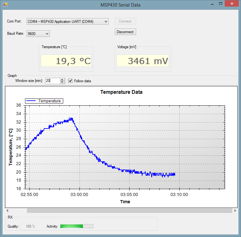
Windows Xp Key Generator Sp3. Here is a semi-pseudo code excerpt from the C# program where I calculate temperature Msp430 serial code example. ADCValue is the 10 bit value read by the ADC.

First, we need to ensure we have our DCO set to our custom calibration. The way I've chosen to do this is to use definitions in the header: #define CALDCO_UART *( char *)0x10BE #define CALBC1_UART *( char *)0x10BF Then in our code, we can set the DCO just as we would for the 1 MHz calibration: BCSCTL1 = CALBC1_UART; DCOCTL = CALDCO_UART; To make this even easier, you can put the #defines in a header file (I've called mine calibrations.h), and then include it in any program where you need to use the custom DCO calibration. Now to set up our timer. First, we need to choose our transmission rate. The commonly selected rate is 9600 baud, and if you use only the LaunchPad's USB connection it may be the only rate that works.
(It's a little unclear still how the USB connection is set up-- the MSP430 UART connects to the MSP430 in the emulator, which has separate pins to forward the data to the TUSB chip interfacing with the USB port.) This DCO frequency can reliably do transmission up to a rate of 921,600 baud. Any faster, and there may not be enough time to run the transmission code between bits. The code you can download at the end of the tutorial is configured for 9600 baud. The next thing we need is to know how many clock cycles occur during the time to transmit one bit. We'll transmit at 9600 bits per second, and our clock oscillates at 7,372,800 times per second, so there are 7,372,800/9600 = 768 clock cycles in each bit. (Note that this is exact; there's no fractional part being truncated in this division, which is why we chose this DCO frequency to start with.) This period is often called the bit time. Bit_time = 24576; // bit time for 300 baud bit_time = 768; // bit time for 9600 baud bit_time = 64; // bit time for 115,200 baud The LaunchPad is set up to send the transmission over P1.1.
Looking in the datasheet, we see that this pin can be used as the TA0.0 output –using Timer_A, we can toggle this output when the TAR counter reaches the value stored in TACCR0. We have two options for this: we can use the timer's up-mode so that the counter resets after reaching TACCR0 of bit_time, or we can use continuous mode and reset TACCR0 to be bit_time cycles beyond the current value of TAR when it triggers an interrupt. Prahar Movie Cast.
(Doing this automatically accounts for roll-over.) The first would be an easy solution for our transmitter, but as we're working towards a full-duplex receiver/transmitter, and the receiver looks at P1.2 (using TA0. Pro E Torrent Download on this page. 1, based on TACCR1 for timing, of course), it makes more sense to use the second method in anticipation of setting up the receiver next time so that we don't have conflicts in using the timer for both tasks. The idle state for UART is logic high. When we configure the timer, we'll ensure that the TA0.0 defaults to setting P1.1. There's no need to start the timer until we're ready to transmit, but on the other hand there's no need to stop it unless you're concerned about power consumption. We'll go ahead and let the timer run for now, since as a peripheral it runs independently and won't interfere with any code running.