Usb To Serial Converter Using Atmega8

Since the ATMega8 doesn't sport a USB controller you have to use, either a serial/parallel connection or get a USB-serial converter which simply installs a driver on the host PC so that the whole connection will look like a serial(emulated) link so you can use just about any program to talk to your controller. Also don't forget to use a RS232-TTL serial level translator lke MAX232.

If all that sounds to summarised you can do the following: Get a USB-Serial converter and install it on your PC Also use a MAX232 or similar IC as a level translator for your microcontroller(ATMega8) Decide on a buad rate and other serial settings like pariy. You can immediately test your code with the built-in utility program called Hyper Terminal that comes preinstalled with most windows versions. Hi, i have a program for connecting atmega8 with usb, and send data from avr to PC. But when i debug the code with avr studio, these errors appear' undefined reference to `usbPoll, undefined reference to `usbMsgPtr', undefined reference to `usbInit'. And when i include 'usbdrv.c' in main function this is the error 'undefined reference to `usbCrc16' this variable is in 'usbdrv.c' i am beginner, could someone help me please? I have attached source codes.[/code] hey u find anything related to it.
I am in need.please reply soon.
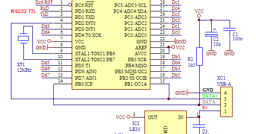
Because the ATmega8 there is no facility for communication with the USB, then inevitably the data with the USB communication protocol must be made on the firmware itself. For a study guide the USB protocol can be seen in other parts of this website or click the link below to view it. In the firmware can be downloaded existing code to handle USB protocol, so that can be directly used, but if you want to add another facility, you can edit the firmware. The firmware provided is written in assembler language that can be done and compiled with AVR Studio 4. Delf B2 200 Activities Free Download there. In addition to code Assembl ernya also included his Hexa code compilation results of AVR Studio 4 which can be directly entered in his IC. Here is a circuit schematic drawing USB to Serial converter with ATmega8. Oregon Trail 5th Edition Torrent Mac.
USB data line of D + and D - connected to PB0 and PB1 in the ATmega8, this connection should not be changed because of these pins can be done with high-speed data transfer. For there was a connection and the opinion of a good signal between USB and devices, then ATmega8 be hired at Low Speed data rate that is the way her pull -up 1k5 Ohm resistor on the D- line data. For the other components are only used as a complement for the system to beropersai with good, for example Xtall used as a clock and used as a filter capacitor power supply.
If at this circuit you want a USB to RS - 232 converter then you need to add the IC MAX 232 as Level converter from TTL to RS232 levels. If you only want to use to control the LED you can directly connect to the PIN I / O directly in series with a resistor before. For the implementation of the firmware as the USB receiver and coding of protocolnya, will receive all the packets of data from USB and then stored in an internal buffer.
Starting from the first revenues derived from external interrupt ( INT0 ) is the data to ' sync pattern ', during the admissions process only the last packet in the check the signal EOP ( End of Packet ). After the admissions process successfully, the next firmware will mong - coding a number of data packets it receives and then analyze it. Once again because of the USB protocol is very difficult you can read again the USB protocol on the following links. The process of receiving data on a USB in general can be seen in the following flowchart flow. Firmware is generally divided into several sections main blocks, namely: * Interrupt Routine * Decoding Routine ( Includes NRZI Encoding, BitStuffing Removal / Addition ). * USB Reception * USB Transmission * Requested Action Decoding * Performing Custom Actions Requested Users can add the function of certain functions into the firmware, like the function to create a ' Customer - Specific ', function to ' Direct Pin Control ' and so forth.
To complete the firmware can be downloaded at the bottom. Driver Nvidia Model P561 more. For ATmega8 that will be used the following support for 800 -byte FIFO buffer, with baudrate baudrate 300 to 115 200, databit ( 5,6,7,8 ), stopbit ( 1.2 ), and its parity ( none, odd, even, mark, space ). By using this ATmega8 there are some possible features that can be added for example: * USB read / write to internal memory that is 512 byte EEPROM to store data such as calibration data or data product code. * Possibility to use PWM and ADC ( Analog to Digital Converter ) which is in ATmega8. * With the program memory space that is still large, the user can add other facilities such as for USB to I2C converter or USB to Serial PS2 and converter - converter to another.